Introduction
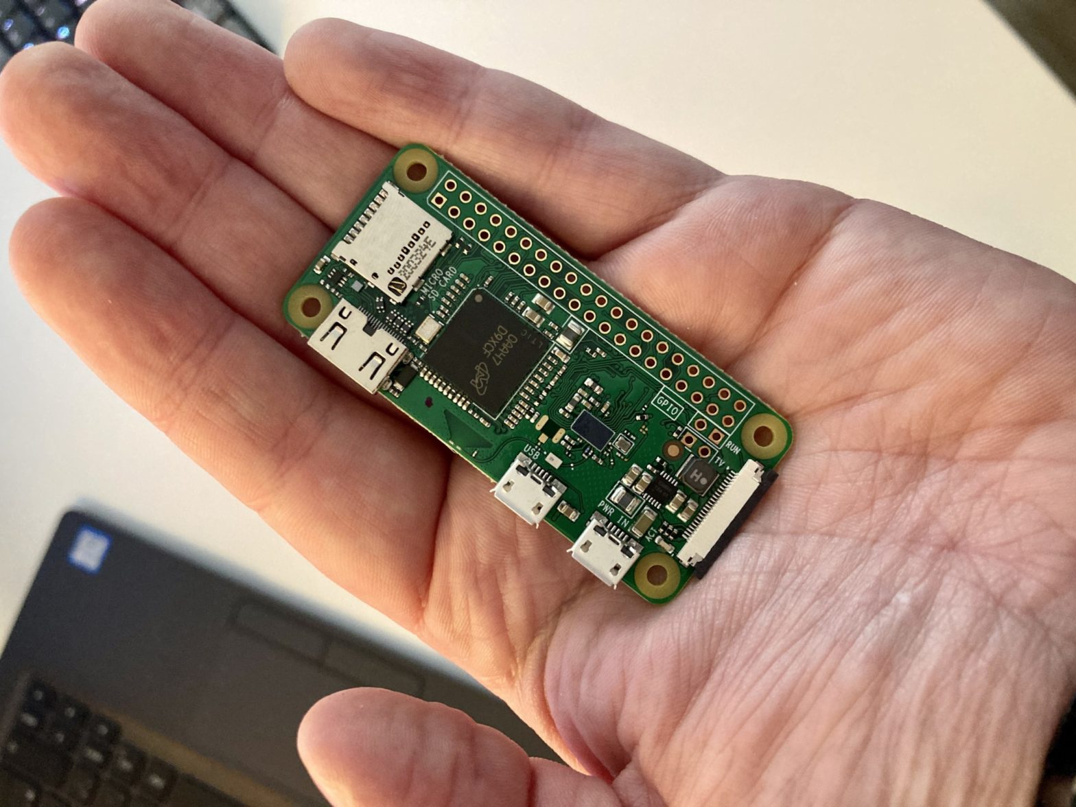
There’s this light in my neighbour’s back yard, which randomly toggles all through the night. It really had an influence on my sleep. At first I thought it’s probably simply a cat or something, triggering a motion sensor. But then I realized that it toggles periodically. The social and open person I am as an IT guy, I did not just go to the neighbours and talked to them. Instead, I wanted to find out the actual period of the light. Way more interesting. So I figured, let’s get one of those fancy new Pi Zeros and measure the light through a couple of nights.
This article will show you two approaches in terms of hardware on how to measure the light with a raspi. There’s a DIY approach, which consists of two resistors, a capacitor and a photodiode all for 67 cents. Then, there’s a modular approach, which consists of a BH1750 light sensor connected via I2C around the 3-5€ mark.
The DIY Approach
How it works
I found this solution in a MagPi magazine article by Simon Monk. The idea behind this is genius. The Pi doesn’t have any analog GPIOs, only digital ones, so you can’t simply measure a resistance, for example. However, you can measure time. Take a look at the following breadboard:
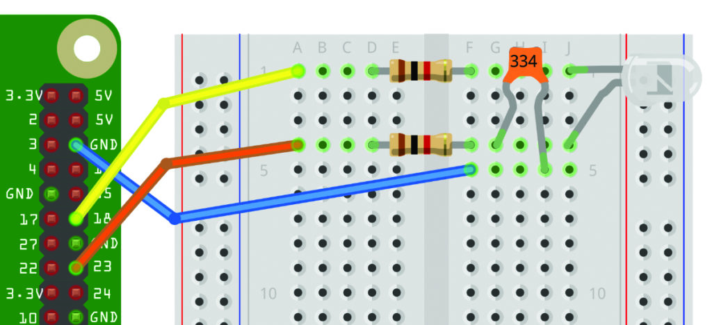
If the value of the capacitor is known, the time it takes to charge it and then pull up another GPIO afterwards can be calculated. With that time, the resistance of the photodiode can be calculated. Genius, isn’t it!?
The code can be found at Simon’s GitHub repo.
Limitations & Workarounds
I stumbled into the problem of darkness. The darker it gets, the longer it takes to charge the capacitor. In my case, it often took 5-10 seconds until the libraries’ read_resistance() returned. Furthermore, the calculated value will then be negative. It probably also depends on the sensitivity of the photodiode. I don’t have any experience on that field. However, I’ve tried a hand full of photodiodes and had the best results with a BPW42 (3mm).
Code-wise, I implemented two solutions to interrupt the measuring routine after a certain timeout. You can either use a signal handler with SIGABRT or call the measuring routine in a thread and call t.join(timeout). The signal() approach is a little more fiddly in my opinion, not only because signal should only be called in main(). I’d prefer the concurrent approach, because it also makes the code more readable.
#!/usr/bin/python3

from PiAnalog import *
import time
import math
import signal
import sys
from struct import *
from datetime import datetime
from threading import Thread
from pprint import pprint

# globals
p = PiAnalog(C=0.047)

def sigIntHandler(sig, frame):
    print('Bye.')
    global logfile
    logfile.close()
    sys.exit(0)

def sigAlmHandler(sig, frame):
    raise BaseException("Time's up.")

def lFromRes(res):
    # Log the reading to compress the range
    return math.log(1000000.0/res) * 10.0

def readL():
    r = p.read_resistance()
    lstr = "{:.1f}".format(lFromRes(r))
    return lstr

def printRow(l):
    tnow = time.time()
    ostr = "%d    %s" % (tnow,l)
    print(ostr)

class ReThread(Thread):
    def __init__(self, group=None, target=None, name=None,
                 args=(), kwargs={}, Verbose=None):
        Thread.__init__(self, group, target, name, args, kwargs)
        self._return = None
    def run(self):
        if self._target is not None:
            self._return = self._target(*self._args, **self._kwargs)
    def join(self, *args):
        Thread.join(self, *args)
        return self._return

def main():
    signal.signal(signal.SIGINT, sigIntHandler)

    # Thread Version
    while True:
        t = ReThread(target=readL)
        t.start()
        res = t.join(5.0)
        if res is not None:
            printRow(str(res))
            time.sleep(1)

    # Signal Version
    while True:
        oh = signal.signal(signal.SIGALRM, sigAlmHandler)
        signal.alarm(5)
        l = "0.0"
        try:
            l = readL()
        except BaseException as ex:
            print(ex)
        finally:
            signal.signal(signal.SIGALRM, oh)
            signal.alarm(0)

        printRow(l)
        time.sleep(1)

if __name__ == "__main__":
    main()
The Module Approach
How it works
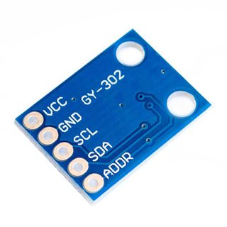
There’s a ready to use light sensor module BH1750. However, you need to pay attention, because the simple version is digital and will only deliver 0=dark or 1=bright. However, there’s also a variant for I2C usage on the market, which is what you want, if you’re reading this article, I presume.
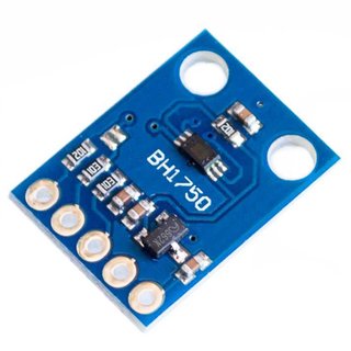
The module has a couple of advantages over the cheap DIY approach. First, it responds quicker without the need for a timeout. The response time was around the three digit millisecond ballpark every time I’ve tried. Second, it comes with a sensitivity register, which enables you to set the sensitivity as low as 0.1 lx. See the code below for how to set the sensitivity.
Wiring & Testing
Wire it up as follows:
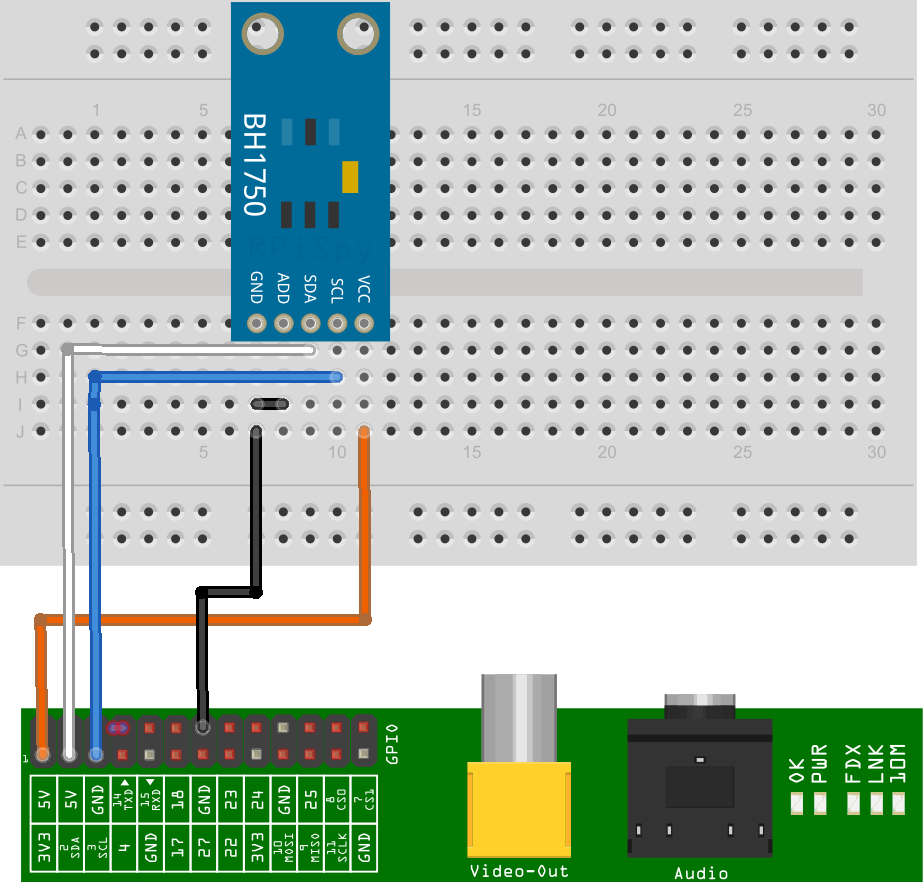
Note that the Address pin is wired to ground. This will lead to an address of 0x23.
You can test the module by running i2cdetect (part of the package i2c-tools):
$ i2cdetect -y 1
     0  1  2  3  4  5  6  7  8  9  a  b  c  d  e  f
00:          -- -- -- -- -- -- -- -- -- -- -- -- --
10: -- -- -- -- -- -- -- -- -- -- -- -- -- -- -- --
20: -- -- -- 23 -- -- -- -- -- -- -- -- -- -- -- --
30: -- -- -- -- -- -- -- -- -- -- -- -- -- -- -- --
40: -- -- -- -- -- -- -- -- -- -- -- -- -- -- -- --
50: -- -- -- -- -- -- -- -- -- -- -- -- -- -- -- --
60: -- -- -- -- -- -- -- -- -- -- -- -- -- -- -- --
70: -- -- -- -- -- -- -- --
Code
The BH1750 lib taken from here
#!/usr/bin/python3

import smbus
import time

class BH1750():
    """ Implement BH1750 communication. """
    # Define some constants from the datasheet
    POWER_DOWN = 0x00 # No active state
    POWER_ON   = 0x01 # Power on
    RESET      = 0x07 # Reset data register value
    # Start measurement at 4lx resolution. Time typically 16ms.
    CONTINUOUS_LOW_RES_MODE = 0x13
    # Start measurement at 1lx resolution. Time typically 120ms
    CONTINUOUS_HIGH_RES_MODE_1 = 0x10
    # Start measurement at 0.5lx resolution. Time typically 120ms
    CONTINUOUS_HIGH_RES_MODE_2 = 0x11
    # Start measurement at 1lx resolution. Time typically 120ms
    # Device is automatically set to Power Down after measurement.
    ONE_TIME_HIGH_RES_MODE_1 = 0x20
    # Start measurement at 0.5lx resolution. Time typically 120ms
    # Device is automatically set to Power Down after measurement.
    ONE_TIME_HIGH_RES_MODE_2 = 0x21
    # Start measurement at 1lx resolution. Time typically 120ms
    # Device is automatically set to Power Down after measurement.
    ONE_TIME_LOW_RES_MODE = 0x23

    def __init__(self, bus, addr=0x23):
        self.bus = bus
        self.addr = addr
        self.power_down()
        self.set_sensitivity()

    def _set_mode(self, mode):
        self.mode = mode
        self.bus.write_byte(self.addr, self.mode)

    def power_down(self):
        self._set_mode(self.POWER_DOWN)

    def power_on(self):
        self._set_mode(self.POWER_ON)

    def reset(self):
        self.power_on() #It has to be powered on before resetting
        self._set_mode(self.RESET)

    def cont_low_res(self):
        self._set_mode(self.CONTINUOUS_LOW_RES_MODE)

    def cont_high_res(self):
        self._set_mode(self.CONTINUOUS_HIGH_RES_MODE_1)

    def cont_high_res2(self):
        self._set_mode(self.CONTINUOUS_HIGH_RES_MODE_2)

    def oneshot_low_res(self):
        self._set_mode(self.ONE_TIME_LOW_RES_MODE)

    def oneshot_high_res(self):
        self._set_mode(self.ONE_TIME_HIGH_RES_MODE_1)

    def oneshot_high_res2(self):
        self._set_mode(self.ONE_TIME_HIGH_RES_MODE_2)

    def set_sensitivity(self, sensitivity=69):
        """ Set the sensor sensitivity.
            Valid values are 31 (lowest) to 254 (highest), default is 69.
        """
        if sensitivity < 31:
            self.mtreg = 31
        elif sensitivity > 254:
            self.mtreg = 254
        else:
            self.mtreg = sensitivity
        self.power_on()
        self._set_mode(0x40 | (self.mtreg >> 5))
        self._set_mode(0x60 | (self.mtreg & 0x1f))
        self.power_down()

    def get_result(self):
        """ Return current measurement result in lx. """
        data = self.bus.read_word_data(self.addr, self.mode)
        count = data >> 8 | (data&0xff)<<8
        mode2coeff =  2 if (self.mode & 0x03) == 0x01 else 1
        ratio = 1/(1.2 * (self.mtreg/69.0) * mode2coeff)
        return ratio*count

    def wait_for_result(self, additional=0):
        basetime = 0.018 if (self.mode & 0x03) == 0x03 else 0.128
        time.sleep(basetime * (self.mtreg/69.0) + additional)

    def do_measurement(self, mode, additional_delay=0):
        """
        Perform complete measurement using command
        specified by parameter mode with additional
        delay specified in parameter additional_delay.
        Return output value in Lx.
        """
        self.reset()
        self._set_mode(mode)
        self.wait_for_result(additional=additional_delay)
        return self.get_result()

    def measure_low_res(self, additional_delay=0):
        return self.do_measurement(self.ONE_TIME_LOW_RES_MODE, additional_delay)

    def measure_high_res(self, additional_delay=0):
        return self.do_measurement(self.ONE_TIME_HIGH_RES_MODE_1, additional_delay)

    def measure_high_res2(self, additional_delay=0):
        return self.do_measurement(self.ONE_TIME_HIGH_RES_MODE_2, additional_delay)


def main():

    #bus = smbus.SMBus(0) # Rev 1 Pi uses 0
    bus = smbus.SMBus(1)  # Rev 2 Pi uses 1
    sensor = BH1750(bus)

    while True:
        print("Sensitivity: {:d}".format(sensor.mtreg))
        for measurefunc, name in [(sensor.measure_low_res, "Low Res "),
                                  (sensor.measure_high_res, "HighRes "),
                                  (sensor.measure_high_res2, "HighRes2")]:
            print("{} Light Level : {:3.2f} lx".format(name, measurefunc()))
        print("--------")
        sensor.set_sensitivity((sensor.mtreg + 10) % 255)
        time.sleep(1)


if __name__=="__main__":
    main()
The lib needed slight modification, because it was written with python 2.7. However, only the main() function was affected. The rest of the lib worked out of the box as far as I remember.
If you call the main-function of the lib itself, it will iterate through the possible intensities of the sensor and print the results of all possible measurement-functions for each sensitivity. This really helped me, to find the right sensitivity for my situation.
The main py
#!/usr/bin/python3

import smbus
import time
import math
import signal
import sys
from struct import *
from datetime import datetime
from threading import Thread
from pprint import pprint
from bh1750 import *

i2cbus = smbus.SMBus(1)
sensor = BH1750(i2cbus, addr=0x23)

def sigIntHandler(sig, frame):
    print('Bye.')
    global logfile
    logfile.close()
    sys.exit(0)

def printRow(l):
    tnow = time.time()
    ostr = "%d    %s" % (tnow,l)
    print(ostr)

def bh1750Loop():
    sensor.set_sensitivity(254)
    print("Sensitivity: {:d}".format(sensor.mtreg))
    while True:
        l = sensor.measure_high_res()
        printRow(format(l,'.3f'))
        time.sleep(1)

def main():
    signal.signal(signal.SIGINT, sigIntHandler)
    bh1750Loop()
    sys.exit(0)

if __name__ == "__main__":
    main()
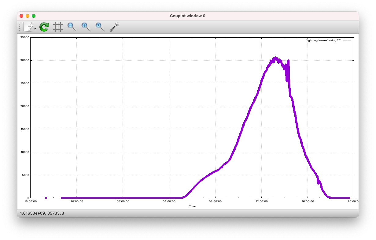
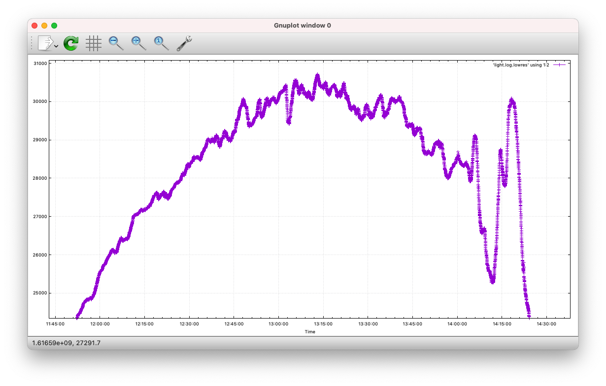
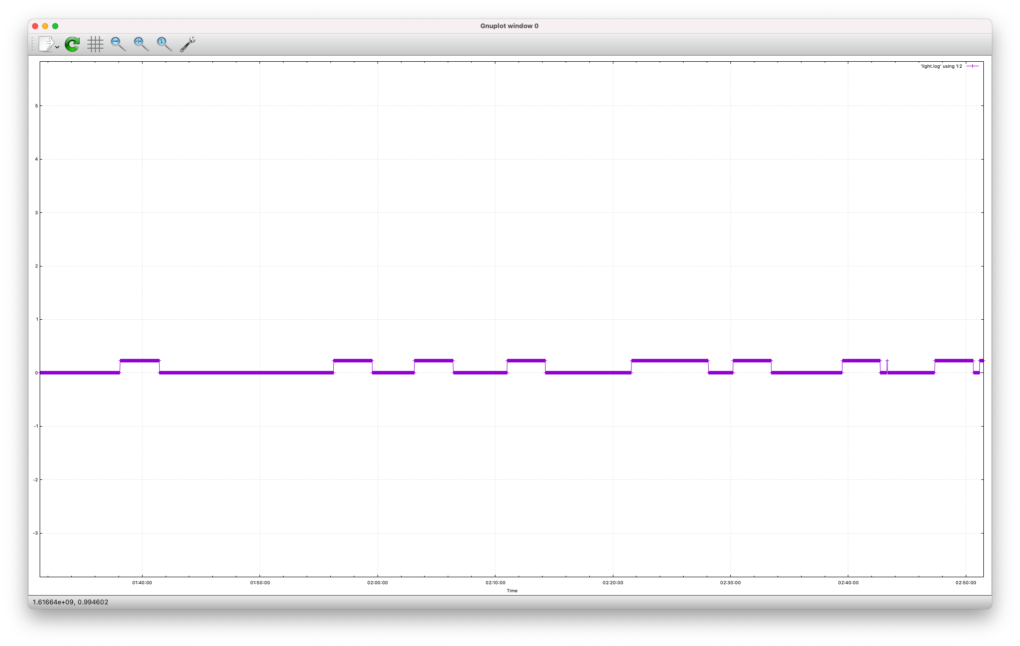
Sample Result
The following plots were captured in a 24 hour period on March 25th, 2021 in Frankfurt/Germany. The very last plot shows the result I was looking for. It shows the frequency of the light in the back yard turning on and off all through the night. However, the reoccurrence seems to be random after all. Good thing I’m moving next week.
Oh and for whoever it might need, here’s the plot script for Gnuplot. Adjust to taste, it’s pretty basic. One thing, though: I saved the time as unix timestamps. Gnuplot can easily format those.
set term qt
set xlabel "Time"
set timefmt "%s"
set format x "%H:%M:%S"
set xdata time
set grid
plot 'light.log' using 1:2 with linespoints